


The Persuader from MOD Kits DIY (available at modkitsdiy.com for about $65) is a U-build-it, starved plate, 12ax7 distortion box kit. It arrives as a collection of parts to be assembled into a powder-coated purple, pre-drilled Hammond-style cast-aluminum box. A 16 page assembly manual identifies all the included components, and has a solid, but brief tutorial on soldering. At the end of the manual are various tear-out drawings to use as guides in the build process. The step-by-step build instructions were clear, and if you’ve built a few kits of reasonable complexity, it’s fairly straight-forward to build The Persuader. There were one or two steps in the build I thought were not in ideal order; I’ll address those later in this review.
Notes from the build:
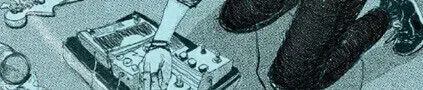
I was surprised the kit is point-to-point wired on terminal strips. I was expecting it to be a PCB build. Assembly took me 3 to 4 hours in spite of having being interrupted a few times. If you’re good at this sort of thing, it should take only a couple hours. I wouldn’t recommend this kit to a first-time builder; you can see from the pictures the finished build is fairly dense. If you’ve built a few kits, made your own DIY pedals, or done any modification work to your own amplifiers, you’ll probably be fine. Definitely read through the instructions until you understand them before starting, and go slowly, ticking off each step as you complete it. If you take your time, The Persuader is a fun little kit to build.
By and large, the kit is well designed and implemented. The only finish issue I had was the enclosure’s cutout for the power jack was a little too large, and required a bit more force than expected to seat firmly. The stereo input jack was a real Switchcraft #12, but the output jack was a flimsy generic unit that bent out of shape the first time I plugged a guitar cable into it. I’m sure MOD Kits would have sent replacement without any hassle, but I already had a Switchcraft #11 floating around and just replaced the broken jack with that.
Some suggestions I’d make in addition to the manual’s instructions:
First, take a sharpie and number the inside of the enclosure with the lug numbers of the terminal strips. This will make the build substantially easier as all the mounting instructions refer to terminal numbers.
Secondly, break from the build instructions and mount the MOSFET last. This is really the only fragile part of the kit (outside the glass tube), and the instructions have it mounted early in the process. Mounting it last should help prevent it from damage from static electricity or being cooked by the soldering iron.
Thirdly, the color PDFs from MOD Kits’ site are easier to follow than the black and white print outs provided, and a schematic of the circuit (not included in my kit), can be freely downloaded from MOD kits’ site. When I built The Persuader, I installed the MOSFET upside-down, and destroyed it when I powered the unit on. It’s a little hard to tell which side is up from the B&W instructions, but this is easily discernible from the color PDF. MOD Kits were great about sending me a replacement MOSFET, which I received in a couple days after requesting it. At that time, they also sent me a troubleshooting supplement with a handy chart of what voltages should be present at various test points throughout the circuit.
Other things that helped me in the build (but aren’t necessary) are some small pieces of shrink wrap to insulate component leads from shorting against other parts (you also could use the stripped insulation from the hookup wire), and I used a dollop of hot glue to keep the large filter cap on the DC jack from stressing its solder points.
The manual stresses this, but it bears repeating: the pots come very close to the terminal strips on either side of the tube; be careful to not short these against one another. If you’ve got some spare 12mm pots of like value floating around (5K linear, 250K log), and if they’ll mount cleanly in the enclosure, substituting those will give you a bit more room to move.
Both the manual and the catalog that comes with the kit state that “this pedal draws considerable current and battery life will be short”. Given that the MOSFET, tube plates and more importantly, the filament of the tube are all powered by the same battery, I trust this is going to be the case. With that in mind, and that there’s no battery holder included, I consider the battery clip optional, and think the battery space is better suited for modifications. After completing the build, I actually removed the clip so it wouldn’t rattle around in the enclosure.
In use/ Tone
The Persuader is a two stage circuit. The first is a MOSFET boost stage which pushes the signal into the second (tube) stage for distortion. The GAIN control adjusts the gain of the MOSFET, and VOLUME adjusts the overall level out of The Persuader. At low gain settings, The Persuader is almost a clean boost, and is capable of a fairly substantial level increase. At about 12:00 on the GAIN knob, distortion begins to creep in. Between 12:00 and 3:00, The Persuader settles into a nice, bluesy, touch sensitive distortion. Between about 3 and 4 o’clock, the distortion becomes a little nastier, and most of the dramatic change in the character of the distortion happens between 4 and 5 o’clock. Full-out, The Persuader is a really trashy, ’60s kind of overdrive. Think early Kinks, Communication Breakdown, that sort of thing. I let a friend of mine try this with a 335 into an old pawn-shop Magnatone Model 401, which sounded fantastic. With the gain at about 3 or 4 o’clock, this set up was chucking out a great over-driven sound, much closer to speaker break-up than preamp saturation to my ear. We compared The Persuader to my friend’s Vox CoolTron Big Ben, and he preferred The Persuader. I think I liked the VOX a little better, as it’s got a smoother distortion, but as my friend said, The Persuader’s got more personality.
The overall signal quality of The Persuader is good. In spite of having a lot of gain on tap, it’s fairly clean at moderate gain settings. It will hiss at higher gain settings, but what distortion box doesn’t? The only thing that’s a little bit of a bummer in terms of noise is the GAIN knob is a bit scratchy, especially when going from moderate to higher settings. The Persuader also wants a regulated power supply, as the generic supply I used caused a fair amount of hum. This wasn’t a problem with a Voodoo Labs unit.
The strong suit of The Persuader to me is its touch-sensitivity. One of my favorite things about playing guitar into a loud sounding setup is being able to play gently and have clean tone, and then jumping on the strings and having everything get gritty. Very satisfying. The Persuader does a good job of this. It also complimented my JCM800 nicely by having the JCM set to fairly low input gain, and using The Persuader as a semi-clean boost to overdrive the input of the Marshall. I’d recommend this pedal to guitarists looking for a simple, yet flexible boost/ grit box.
Functionally, I have a few minor complaints. First, it’d have been nice to have an LED status indicator, but I suspect with the low price of the kit and that adding an LED to the works would require a 3PDT switch to keep the pedal true bypass, the LED was omitted with good reason. Next, I’m a little afraid I’ll jam my foot through the tube holder at some point when I’m not paying close attention to what I’m doing when I go for the footswitch; they’re are a little under two inches from one another. Lastly, the adapter socket is located in a bit of a weird place, all the way at the front of the unit. Granted, that was pretty much the only place left to mount it, but I’d rather the input jack and DC socket traded places, and that the internal battery was omitted to accommodate that placement if necessary.
Proposed modifications:
After playing with the completed Persuader for about a week, it occurred to me it might be nice to have a tone control. The only place left to put one would be to side-mount a pot where the battery goes for a simple hi-cut tone control. Alternately, and probably more usefully, I may end up using that same space to put in another footswitch. This would be a SPST switch that would kick the input gain knob to full volume to make this a two stage boost pedal. This would be a pretty easy mod—you’d just need to jumper the MOSFET’s source to ground).
Some last things I’d like to suggest to MOD Kits: thinner hookup wire might be a good idea. The included hook-up wire was a fairly thickly insulated, 22AWG wire. Working with slightly thinner wire or wire with thinner insulation would help soldering in some of the tighter spaces in the pedal. A larger enclosure that would allow for internally mounting the tube would alleviate the danger of stepping through the tube. Lastly, I love building this kind of project to learn how and why a given circuit works. To that end, It’d be great to have a circuit description included in the kit or available for download.
Ron Guensche is a San Francisco Bay Area bassist / audio engineer and plays in the bands Gentlemen and Spidermeow.